Valve Adjustment
By: Dano
Link to this page:
BACK TO PRELUDE3G.COM HOME
(MC's Note: I took some pics when I did mine recently, scroll to the bottom to see them.)
First some background:
Why is there an air gap (clearance ) anyway ?? Because metal expands with heat, an air gap is needed to make sure that the valve is allowed to snap COMPLETELY into it’s seat. If a valve were to be open a mere .001" during the power stroke, it will soon burn to a crisp. As you can imagine, the exhaust valves get hotter than the intake valves which explains their larger gap. With "cam in block" engines (domestic V8’s for example) the expansion problem is much worse with the long push rods. That is why, rpm limiting, hydraulic valve lifters are used. Hehehehe.
The Honda Prelude twin cam SI engine (3rd gen on) has a pretty noisy valve train. To begin with, it does not use rocker shafts like the single cam and VTEC engines. Instead, it uses a solid rocker with a ball stud on one end while the other end sits on the end of the valve stem. If you ever took one apart, you would see that this rocker is a heavy chunk of steel being thrown up and down without the benefit of a rocker shaft acting as a fulcrum. Even if you can get rid of the tapping sounds, you still will hear a distinctive "whirring" sound from the valve train. ( I like it !!) There is nothing wrong with this design. It is super strong with a very large contact surface, plus it can be easily adjusted with great precision.
The sticker on the underside of the hood gives you the proper valve clearances. However, they are listed in hundredths of a millimeter (.01mm). Seeing as how it’s just about impossible (strange) to find true millimeter feeler gauge sets, we need to use the closest equivalent in thousandths of an inch (.001") on the, more common, SAE gauge set. The SAE set usually will show the metric equivalent size too. Whatever you do, avoid the special valve adjustment feeler gauges that some mechanics use. These normally have a .002" Go/ No Go step, which is way too sloppy. Honda advises plus or minus .02mm tolerance. That .002" step equals more than .05mm! ( .001" equals .0254mm)
If you have or are able to get metric gauge sets, use them instead of the SAE sets. The .02mm tolerance Honda specifies is a bit smaller and therefore, more precise than our .001" tolerance.
We will be using the "Go" / "No Go" method with a tolerance of only .001". Especially on an engine with oil present the "slight drag on the feeler gauge" method is just too subjective. You can have a "slight drag" on the feeler gauge and still insert gauges .002" and even .003" larger. Wonder why you still have valves tapping after an adjustment ???
For 88-91 Prelude SI , B20A5, B21A1 engines ( +/- means …"plus or minus" ) .10mm +/- .02mm for intake valves equals .004" +/- .001" .18mm +/- .02mm for exhaust valves equals .007" +/- .001" For 92-95 Prelude SI, H23A1 engine ---- Go to the end of the article
Let’s get to work…… I’m assuming the valve cover is off and the engine is cold.
Inside the fender well , you will find a rubber plug that, when removed, allows access to the crankshaft pulley nut which you will be turning counter clockwise .
Pull out the sparkplugs to make it easier to turn the engine.
Adjusting the valves:
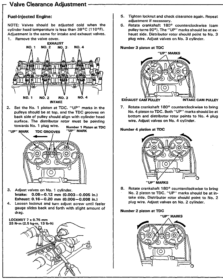
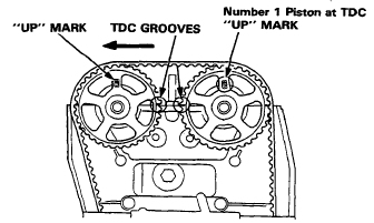
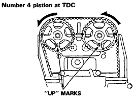
Manually turn the engine so that the "UP" arrows on
the camshaft sprockets are pointing up. This means that the #1 piston is at
the top of it’s compression stroke and therefore, ALL valves for that
cylinder will be closed. It is not necessary to be absolutely precise here.
Remember, all valves will be closed for just about all of the upward compression
and the downward, power stroke, so if the arrows are off a few degrees it
really won’t matter.
To avoid confusion, I use two sets of feeler gauges…one for intake the other for exhaust.
Pull out the .004" and the .005" gauges for the intake valves. ( "Go" and "No Go" sizes )
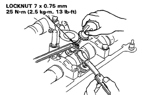
I would recommend the use of a socket and an extension to loosen up the adjusting screw jam nut (saves knuckles) and a box end wrench to re-tighten it. I don’t use a torque wrench for this step, but the correct torque for the jam nut is 20 ft. lb.
From the center of the engine slip the .004" gauge between
the rocker and the camshaft. It will probably slip through easily. .. Now
try the .005" gauge.. Does it slip through too ?? If it does , there
is too much gap. Loosen up the jam nut with your socket wrench. Now Put your
box end wrench on the nut and using a large screwdriver, turn the adjustment
screw clockwise a little and re-tighten the nut a bit with the wrench. Try
again. Does the .004" gauge still slide through ?? Does the .005"
gauge still slide through ?? If it does , run the adjusting screw down a little
bit more, and try again.
Depending on how much crud there is in your adjustment screw and jam nut , you may have to use the screwdriver to hold the screw in place while you re-tighten the nut. If you don’t … re-tightening the nut can also turn in the screw, messing up your adjustment.
With some patience you will get the .004" gauge to slide through but the .005" gauge will NOT. Now tighten down the jam nut firmly with the wrench.. Re-check clearances. The clearance is now something BETWEEN .004" and .005".
Now you can move on to the other intake valve. When you get that adjusted. You can move to the exhaust valves. You follow the same procedure except now your two gauges will be .007" and .008" . (you can do the exhaust valves first if you want to)
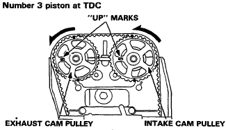
When you are done with the exhaust valves, you can move on to the next cylinder in the firing order which is #3 . ( 1 - 3 - 4 - 2 )
#3 Cylinder… Manually crank the engine (counter clockwise
) until the "UP" arrows both point towards the front of the car.
Repeat the adjustments.
#4 Cylinder… Manually crank the engine until the "UP"
arrows are pointing down.. Repeat the adjustments.
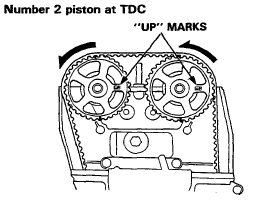
#2 Cylinder… Manually crank the engine until the "UP"
arrows are pointing towards the firewall. Repeat the adjustments.
If you are not fully confident about the adjustments, you can go through the firing order again just to re-check your work.
This sounds like a lot of work and it is time consuming , but once you get the hang of it, it will go rather quickly. You will begin to instinctively know how far to turn the screw for the proper adjustment. I have so much confidence with it that I drop down to the low end of the tolerances for *MY* car, using .003" and .006" instead of .004" and .007" for my "Go" gauges . The .004" and .007" now become my "No Go" gauges. When fully warmed up….my engine is pretty quiet.
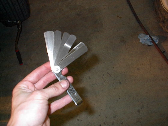
Here's the valve adjustment tools. Flathead screwdriver, 12mm wrench and feeler gauges:
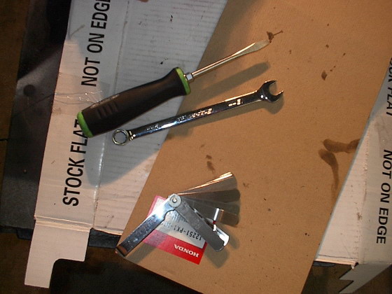
Closer look at feeler gauges:
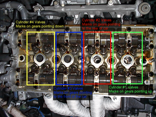
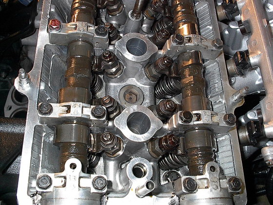
3rd gen DOHC valve train:
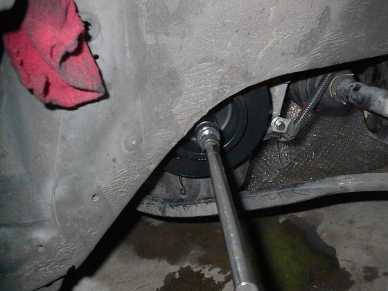
I use a long extension and 19mm socket to turn the crank. In this pic the car is completely on the ground, I turned the wheel all the way to the drivers side and can turn the crank from there:
Loosening adjusting nut on exhaust valve rocker:
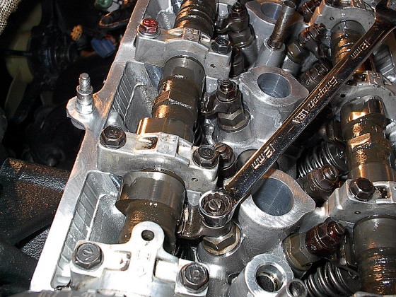
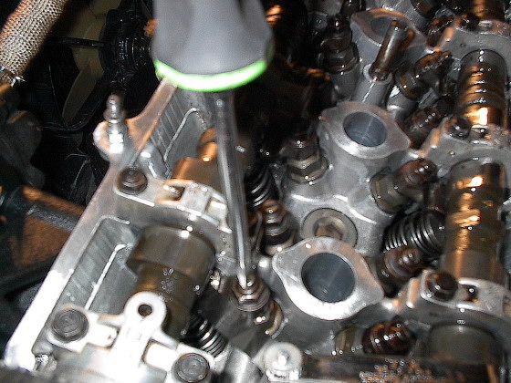
Here I'm turning the adjusting screw and if you look at the bottom of the pic I have a .006" feeler gauge in between the cam and rocker:
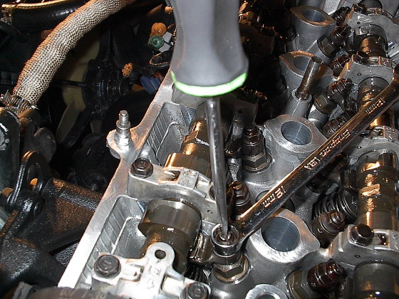
Once you get the desired clearance use the flathead to hold the adjusting screw in place and tighten the nut with the wrench.
More: